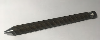
I was not really satisfied with the compound slide's behaviour from the very beginning. If I ever adjusted it for smooth movement, it became loose and unstable in almost any position. When adjusted for better stability and accuracy, it became hard or almost impossible to move using the feed-screw. As I rarely used the compound slide, of course I chose the latter for higher accuracy. But on a nice day, I had found a small piece of rebar on the ground.
Why do I mention that? My grandfather used to tell me: "If you see something on the ground and it's worth more than a piece of sh*t, then you must pick it up!" So I had this piece of rebar apparently useless on my office desk for two weeks, when the idea had finally arrived: why not machine a
pen from this, a
rebar-pen? But this must have a tapered shape of course, so let's have a closer look at the compound slide! Recently I received a letter from someone who has the same machine and the same problem with the compound. It turned out soon that we do not live too far from each other, so he invited me to visit his workshop. Seeing so many creative ideas in his wonderful workshop also inspired me to deal with this problem at last. I spent an entire day in my basement shop. I try to summarize my findings hereinafter. There might be other and better solutions of course, that's mine and nothing more.
 |
| Compound slide gib in original position |
The problem seems to be that the position of the gib strip is somewhat incorrect. I hope it can be seen on the picture that the gib's flat surface does not meet the angled surface of the slide base. The small (but big enough to cause problem) vertical surface on top edge of the base part reduces the useful flat angled surface on it. Considering this certain situation, I realized that the original adjusting screws are pushing the gib at a higher than optimal position, so the gib tends towards the vertical surface instead of lying on the angled one. This way it more or less lies on a line instead of a
surface.
 |
| Drilling angled |
I decided to change the position of the adjusting screws. And also thought that having more screws may result in more precise adjustment. The screws should go somehow lower, but if I drilled the new holes e.g. a millimeter lower, there would not be enough space remaining between the base and the screw heads so I made 6 new threaded holes just in line with the originals, but in a 6 degrees angle downward, so they will hopefully push de gib to lie on the surface on which it is intended to.
 |
| The compound slide with the six new M3 threaded holes |
Here it comes with the new threaded holes and milled angled surfaces for the nuts to lie perpendicularly to the new holes' direction.
 |
| Modified gib position |
In addition I put a one millimeter thick steel strip above the gib to ensure correct placement, then grinded 8.8 class M3 steel screws to have a 90 degrees conic end, and carefully tightened them one by one while moving the base part to be at the actual screw so that the screws formed their own nests in the gib.
Even after the first experimental reassembly of the machine it appeared to be definitely more stable, while the compound feed-screw could also be used like never before. Later it needed some re-adjustment and it is fine indeed since then.
And finally please check out my "famous" rebar-pen specimens:
#stayathomeandmachine


No comments:
Post a Comment